Additional Style Configuration Options
Aside from all of the style configuration options which are defined throught the Isometric Style Configuration interface, OpenPlant Isometrics also has additional options which can only be defined in the particular style.cfg file.
The configuration files for the styles are located in the individual style's config directory as shown below (using As-Build as an example):
...\WorkSpaces\OpenPlantExample\WorkSets\Imperial\Standards\OpenPlant\Isometrics\styles\As-Built\config
To edit the option, open the style.cfg file in a text editor (such as Notepad), edit and save the changes. Note that the each style has its own configuration file, so a change to the AS-Build configuration file does not apply to the other available styles. If working with an AutoPLANT project, the comparable file is named isoproj.cfg.
The following additional configuration options are available:
Coordinate label output order:
The order of the coordinate label members can now be configured.
#-----------------------------------------------------------------------------
# IE_COORD_SWAP
#
#    0    output coordinates in E/N/EL order (default)
#    1    output coordinates in N/E/EL order
#-----------------------------------------------------------------------------
  IE_COORD_SWAP = 0
Configurable field status for loose components
Normally, OpenPlant Isometrics Manager sets loose items to field. Loose items are fittings/pipes for which all ports are spool breaking. It is now optional to not change the status but keep it as is (as specified in the piping design system).
#-----------------------------------------------------------------------------
  # IE_LoosePipeToField
  # IE_LooseFittingToField
  #
  # These settings determine if a loose pipe or fitting is to be forced to field.
  #-----------------------------------------------------------------------------
  IE_LoosePipeToField    = 1
  IE_LooseFittingToField = 1
Hide continuation fasteners:
Allows you to hide fasteners between continuation components in the isometric.
#-----------------------------------------------------------------------------
# IE_HideContinuationFasteners
#
# When set to a value other than zero fasteners between continuation
# components will not be shown in the isometric. The default behavior is not
# to show continuation fasteners
#-----------------------------------------------------------------------------
#  IE_HIDECONTINUATIONFASTENERS = 1
As stated in the comments section above, the default setting is to not display the continuation fasteners. To show the fasteners, set the value to 0.
Plant North Specification
Currently, when piping is skewed from the Plant North axis, this is displayed in the isometric with a hatched triangle showing the offset with the length values of both legs as shown below:
The IE_PlantNorth variable is defined as an invariant origin and a clockwise angle relative to the standard Plant North Direction. The variable is located in the style.cfg file (unique to each individual style) and is defined as shown below:
IE_PLANTNORTH = org.x org.y org.z angleSo if the variable is defined as follows:
IE_PLANTNORTH = O O O 5
Then the Plant North Direction is rotated clockwise 5 degrees from the default north direction and will display as shown below:
Any isometric which is generated using this style will be rotated as the one shown above.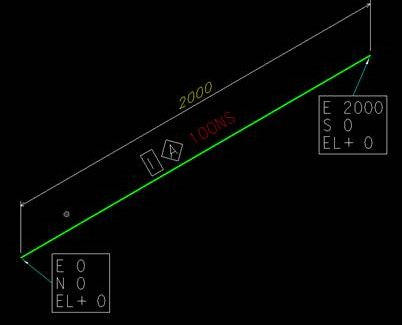
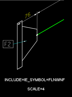
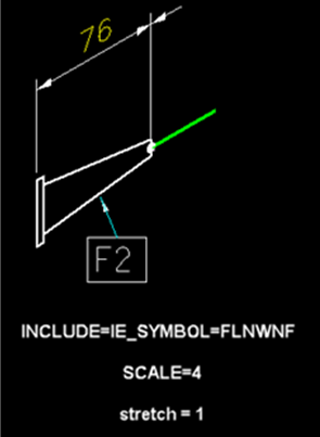
Customizing Text Line Spacing for Labels
To modify the line spacing with multiline labels, you can add a specific configuration variable in the style.cfg (or isoproj.cfg) file for the coordinate cell:<CELL NAME>_SPACING = <value in mm>
PLANTC_SPACING = 1.3Any value below zero is capped at zero.
Setting One PCF.ini for all Isometrics Styles
You can set one PCF.ini for all Isometric Styles. Set the following configuration in isoProj.cfg# Configuration file for creating PCF IE_CFG_PCF = $(IE_CONF)pcf.ini
Setting the Global Origin Values
GLOBAL_ORIGIN=x , y , zand save the file to customize the Global Origin values in an Isometric.
Accessing the Launch Style Editor
You can hide the Launch Style Configuration dialog for users, by adding OPIM_DISABLE_STYLE_CONFIGURATION = 1 variable in the IsoProj.cfg file for the selected Isometric style. It can be accessed from C:\ProgramData\Bentley\OpenPlant CONNECT Edition\Configuration\WorkSpaces\OpenPlantExample\WorkSets\...\Standards\OpenPlant\Isometrics
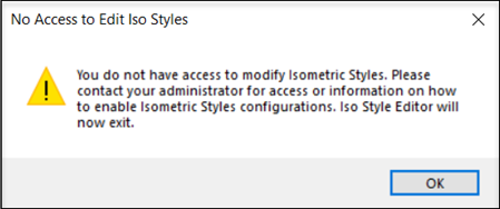
The No Access to Edit Iso Styles dialog appears after adding the variable.